Not Just For Sniper 2 EFI!
I think that the most important thing for me to get right up front is that anyone who decides not to install a Holley's new Power Distribution Module (PDM) because they don't have one of the new Sniper 2 EFI Systems is missing out on a great upgrade for their EFI system. In fact, I would suggest that the PDM has more relevance to the original Sniper EFI System than to the new Sniper 2.
Certainly no one can be faulted for taking a quick look at the "Sniper 2 PDM" and thinking that this is strictly for Sniper 2. In addition to having Sniper 2 in the name, the instructions only show it being used with the Sniper 2 EFI System. No mention of its use with the original Sniper, no mention of its use with Terminator X, and certainly no mention of its use with any other EFI System. I have no idea why Holley would so focus their marketing on this as part of the "Sniper 2 Ecosystem" when the new PDM could be a game changer for so many of the probably tens of thousands of Snipers installed around the world.
Holley Sniper PDM At A Glance
With two 25-ampere and one 15-ampere built-in relay, diagnostic LED's, and 20 ultra-convenient electrical tie-down posts, this is going to cut a hundred dollars of required electrical components and several hours of time from your installation. Then, it's going to dramatically clean up your wiring, allowing you to attach just two included 10 AWG wires to the battery. From there, quickly and easily provide power and ground to your entire EFI system installation. Other small-gauge but critical wire joins go from requiring careful solder and heat-shrink joins to simply stripping and tightening under plated wiring posts. So easy to install, to say nothing about the ease of removing--should that ever be necessary.
How does the Sniper PDM Work?
The PDM instruction manual provided by Holley is a solid introduction to this great product for Sniper 2 owners. Even if you don't have a Sniper 2 EFI System, it will provide you with a general idea of how the team at Holley intended this to be used. But, if you tend to be more meticulous about your installations you may find the instruction manual leaves questions unanswered. At least it did for us. So I dove in to get more answers. Here are some highlights:
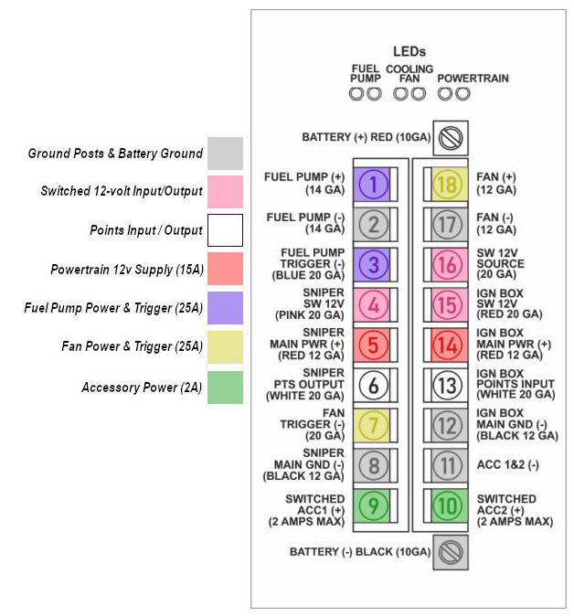 All of the grounding points (Posts 2, 8, 11, 12, and 17) share a single ground plane that is tied to the battery from the GND terminal. (Reference the grey posts in the image at right.)
 - The switched 12-volt power input (Post 16) and suggested outputs to the Sniper and HyperSpark (Posts 4 and 15) share a single plane. There is no filtering of these vital system inputs from what they receive from the switched 12-volt source. (I'll have more to say about this later.)(Shown in pink at right.)
- The points output from the Sniper (Post 6) is a straight-through connection to the points input to the HyperSpark ignition (Post 13.)(Shown in white.)
- 12 volts is continuously available at Post 5 (Sniper Power) and Post 14 (HS Ignition Power) when the PDM is connected to the battery. Holley refers to these as the POWERTRAIN circuits and they have their own ON and FAULT leds. Note that this is not a straight pass-through from the battery. When switched 12v power is not on, a precise 0.5v drop is experienced at pins 5 and 14. In other words,if the battery voltage is 12.72 volts and there is no switched voltage applied to the PDM, the power on pins 5 and 14 will be 12.22 volts. I theorize that this somehow helps reduce battery drain when the system is powered off. When you switch the key on the voltage drop is not experienced, so Posts 5 and 14 are at full battery voltage when the system is running. (Posts 5 & 14 shown in light red.)
- The PDM does indeed draw current when the switched 12 volts is off--even if there is no load on the outputs. The instructions say less than 100 milliamps. That's enough that it should be considered and, in some cases, mitigated. A more typical draw for a vehicle is 50 milliamps. So adding 100 mA potentially triples the static current draw on the battery. A 150 mA draw drains the average battery dead in somewhere just over 2 weeks. Since many of our EFI projects are not daily drivers but intead find themselves sitting between uses, saying that it needs a trickle charger is not an idle suggestion. If that is not convenient then I'd suggest the PDM should be completely disconnected if there are no plans to start the car for more than a week. Easily done by unscrewing the lock-down on the PDM's battery terminal (and just as easily re-installed.)
- The instructions seem to imply a 25 amp current-limit for the fuel pump (Post 1) and fan (Post 18) switched outputs, and that the PDM provides a diagnostic LED alert if a short is detected. In our testing we were unable to light the red FAIL led when we overloaded this circuit. The PDM does seem to limit the current out of these posts but it is clearly still drawing an impressive amount of power since we see the voltage at the PDM's battery terminals drop under 12 volts and stay impacted until the overload is removed. I certainly would have loved to see the circuit interrupted but that is not what we experienced. It's not a deal-breaker, just treat it as you would a normal relay. (Fuel pump trigger and power source shown in blue, Fan trigger and power source shown in yellow.)
Wiring and Fuses
I appreciate that Holley is trying to provide great instruction in the PDM installation manual. But I would encourage folks to be thoughtful when using the wiring gauge recommendations that are printed on the label of the PDM. Sure, in those cases where you're dealing strictly with Holley components you can be assured that those are trustworthy. In these cases they are simply stating the gauge wire that is included for that component (like the switched pink wires or the Sniper power and ground wires.)
But the installer needs to take responsibility for identifying the gauge for wires such as the fuel pump and fan power. This needs to be based on the amperage draw of the device, the length of the wire between the PDM and the device, and the selected fuse. A 14-gauge fuel pump wire may be adequate. Or it may not be. Do your homework.
And I am not comfortable with using no fuses on the 15- and 25-amp outputs of the PDM, as seems to be implied by the wiring diagram in the instruction manual. Certainly, I don't think that Holley is implying by the lack of a fuse on the Sniper power wire that the fuse included in the Sniper 2 main harness can or should be removed if that is being powered from the PDM. But it is not clear if a fuse is recommended on the outputs of the outputs marked Fuel Pump (+) and Fan (+). Were these circuits breaker-style then certainly no fuse would be required. But since our tests didn't indicate that power was interrupted, even under a direct short, I am going to recommend putting in a fuse sized to the lesser of the capacity of the wire or the maximum amperage draw of the device to which it is connected.
How Does The PDM Handle Switched Power?
I am a bit surprised by Holley's decision to use the straight-through connection of posts 4, 5, and 15 for switched power. If there is one thing I recommend on Sniper installations, it's clean up that nasty switched power you're using. A far as I can tell, this part of the PDM design completely forgoes that wisdom. Invariably, the switched power source on these older-model cars and truck carries way too much noise, both from ancient/loose ignition switch contacts and being sourced way to close to coil power. All of which can be cleaned up quickly and easily with a relay.
Were there no way to do with with the PDM I would just say, "Hey, you're going to have to add a relay between your switched power source and post 15." But wait--why not just use those switched accessory posts that are included in the instruction manual without much fanfare? These essentially are the cleaned-up power that we seek, no? True, they only support a maximum of two amps each. And while I have not been able to find a single document that specifies the draw on the Sniper/Sniper 2/Terminator X switched power, or for the HyperSpark switched power, I have been universally told it is less than an amp, and our testing seems to support that. So that's where I tie my Switched 12-volt wires from my ECU and Ignition box.
Ok, So How Do I Use the PDM With My Sniper orTerminator X?
If you stop and look at the PDM in terms of it's components, as described above, I think you'll see that it's just a matter of thinking a bit beyond the uses for each post as suggested on the label. Take the fuel pump power, ground, and trigger, for example (Posts 1, 2, and 3, respectively.) By simply recognizing that you can use this for any ground-enabled accessory drawing less than 25 amps it opens a host of options. Your original Sniper and Terminator X came with a perfectly capable fuel pump relay circuit built right in their main harness. There is no benefit to taking that out and using the fuel pump circuit on the PDM.
Since many of our Sniper and Terminator X customers are controlling two fans independently with their ECUs that means you just relabel the two 25-amp triggered power sources as Fan 1 and Fan 2. Or simply leave the circuit Holley intended for the fuel pump on the Sniper 2 empty until you have another use for it.
Similarly, there is no reason you have to use the Points Output/Input pair (Posts 6 and 13) for that purpose. If you've chosen not to add ECU-controlled ignition timing to your installation, these can be used to tie together any pair of low-voltage wires. One candidate would be the Coil (-) signal that provides the ECU with it's RPM signal in the absence of a crank signal from an electronic ignition.
If you are implementing ECU-controlled ignition timing you will leave the Points Input/Output connected and will also need to determine how to power the HyperSpark or Dual Sync distributor. No source for HyperSpark switched power exists for the Sniper 2 user since Sniper 2 provides power for the HyperSpark directly off the main harness. But no problem, Sniper and Terminator X users can simply tie the HyperSpark pink wire to either post 9 or 10. If you followed my earlier advice to tie the switched power of the ECU and Ignition to these posts we've not had a problem sharing the HyperSpark (pink) or Dual Sync (red) switched power wire with either of these.
True, all of this takes a bit of thought. But if you bought your EFI system from EFI System Pro, that's where your purchase decision really pays off. Simply contact us by phone, email, or chat and let us know what you have in mind. We'll be glad to give you the benefit of our experience. We look forward to these calls--our customers come up with some of the greatest ideas!
 Sniper EFI+
 Terminator X TBI+
 Terminator X MPFI+
 HP-Dominator EFI+
 EFI Components





6 Comment(s)
Will this pdm work with terminator stealth and if so will the instructions you used above work for it? I have the terminator stealth with the hyperspark ignition.
Great question, Douglas. Yes, the PDM will benefit and work with the Terminator Stealth (using the HP or Dominator ECU) exactly as it will the Terminator X (using the Terminator X or Terminator X-Max ECU). From a power and wiring perspective these ECU's are all identical, at least for purposes of this discussion. The differences between the HP/Dominator ECUs and the Terminator X / Terminator X-Max ECU's lie primarily along the lines of their input/output type and capability, and that really doesn't come into play here. I highly encourage the use of the PDM with any of these EFI systems.
PDM turns on and gives 12+ volts from leads 1 and 2, green fuel pump light comes on the PDM. Then power is lost and pump will not run. I’m lost. Pump and wiring are good. Ran straight to battery and pump runs.
To be clear, here's what's supposed to happen when you key the system on for any Holley EFI System: The ECU grounds the fuel pump trigger (the thin blue wire that should be connected to Post 3) for five seconds so the fuel pump comes on to create pressure. It fires the injectors and then removes ground to Post 3 and the fuel pump goes off. The ECU will turn the fuel pump back on when the engine achieves the crank-to-run RPM (normally 400 RPM.) If it doesn't hit that RPM it will never turn the fuel pumps back on. This is an important safety feature to ensure that the fuel pump is not running unless it is supplying fuel to a running engine.
Can I use the unused posts to power other items? I am adding a separate dual air fuel mixture gauge. The control box for the gauge requires a relay….. I was seeing if any of the unused post could be used for that. I’m currently only using posts 1-5, 8 & 16. Says I need a switched circuit… think I could use posts 9, 10 or 11?
Absolutely you can use posts 9 or 10 for any 12-volt switched power requirement. There is no requirement for the target of the power from these posts to be in any way related to the EFI system. The only thing you must do is ensure that the target device amperage does not exceed that of the post which, in the case of 9 or 10, is 2 amps. I certainly would not expect that to be the case for a gauge but be sure to confirm.
Would it be a good idea to run a large, midi fuse close to the battery for the pdm main red wire? Mine will be going opposite side of the engine bay and as I see it, a direct short would caus all kinds of issues until it burned up.
We've remarked among ourselves that it does seem a bit surprising that Holley neither includes nor suggests a fuse for the 12-volt lead to the PDM. I am not aware of any downside to adding a fuse yourself. As you suggest, I think it's value is directly proportional to the length and size of the lead. That being a pretty heavy-gauge wire, and since you're running it all the way around the engine compartment, probably not a bad idea.
Thanks for the great info! Just installed one of these on an original sniper system. Ran into a couple snags and workarounds that I documented here.
Doug's video, linked above, points out the overload situation he got when he connected the battery connection from an original Sniper to the PDM Sniper Main Power (Post 5). As he points out in is video, this is in fact connecting both the Sniper's main power and the fuel pump power supply to Post 5--hence, the overload. I should have made clear that on Sniper 1 you should remove the relay (made unnecessary by the PDM) and wire the resulting loose wires into the PDM as appropriate. You should continue to use the fuse on the Red wire between Post 5 and the Sniper (as Holley does on the Sniper 2 harness.) See my comments above regarding fusing.
Hi Chris great articles Chris i have series1 sniper and PDM I have wired it as t though without the relay The main 12v to 5 , fuel pump + to 1 and trigger wire to 3 and switch 12v to 4 I have no fuelpump until I earth 3 It appears the trigger wire is not earthing Would appreciate some help
Recognize that there are certain conditions under which the fuel pump is triggered. First, the Sniper must have a configuration. If you've not run your setup wizard or otherwise created a configuration, then it will not enable the fuel pump under any condition. Second, at key-on, the Sniper only turns on the fuel pump for five seconds for the fuel pump to prime the lines. After that, it turns it back off and doesn't again activate it until the engine achieves the crank-to-run RPM (normally 400 RPM.) So if the engine isn't running the only chance you have to see the fuel pump trigger enabling the fuel pump is during that five seconds at key-on. If you've confirmed that is not happening then it's time to contact Holley about getting your Sniper back to them for service.
Leave a Comment